EPL200
Compact Open-Frame PLC
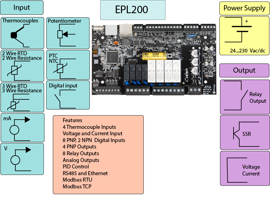
Features
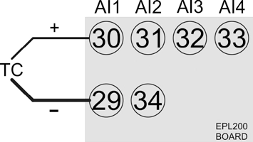
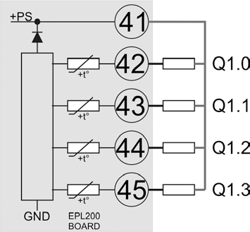
- 4 Thermocouple Inputs
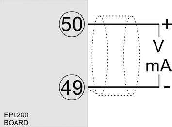
- Voltage and Current Input
- 8 PNP, 2 NPN Digital Inputs
- 4 PNP Outputs
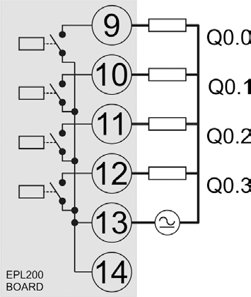
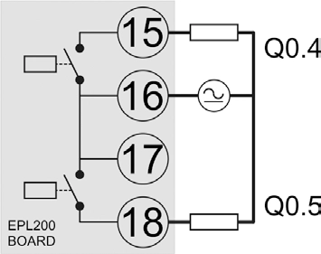
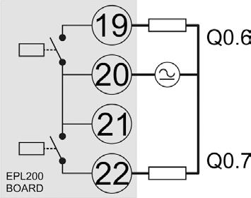
- 8 Relay Outputs
- Analog Outputs
- PID Control
- RS485 and Ethernet
- Modbus RTU
- Modbus TCP
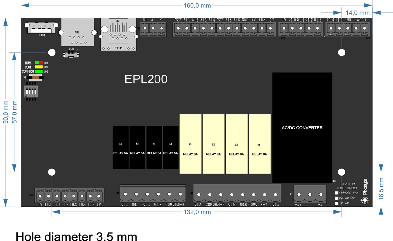
EPL200 Compact Open Frame PLC Board
The EPL200 is a compact and flexible open-frame PLC board designed to function as both a control unit and a connectivity node. It offers integrated RS485 (Modbus RTU), Ethernet (Modbus TCP/IP), and a complete set of analog and digital I/O, making it ideal for embedded control applications.
The board is programmable via the LogicLab development environment, compliant with IEC 61131 standards and available for download in the Software section of this page.
Designed for seamless integration into machines and systems, the EPL200 supports a wide range of input and output signals, multiple encoder inputs, and various power supply options. Its versatility in both mounting and programming makes it a practical alternative to traditional custom electronics.
Key Features
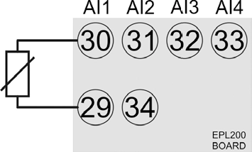
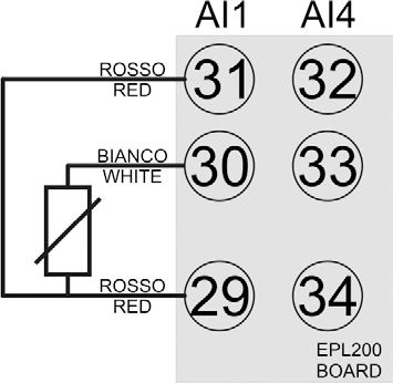
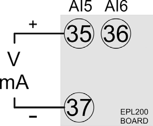
- Wide Input Compatibility: Thermocouples, RTDs, thermistors, mA, mV, and voltage signals.
- Multiple Output Options: Analog voltage or 4–20 mA, digital PNP outputs, and 8 relay outputs.
- Flexible Communication: RS485 (Modbus RTU) and Ethernet (Modbus TCP/IP).
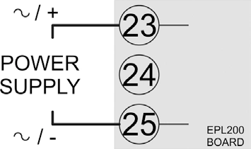
- Power Supply Options: 24 V AC/DC, 12 V AC/DC, or 115–230 V AC.
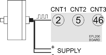
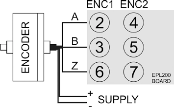
- Encoder Support: Accepts up to 3 encoders for motion or positioning applications.
- LogicLab Programmable: IEC 61131-compliant development environment.
- Open-Frame Design: Ideal for OEM integration within custom equipment and panels.
- Compact and Modular: Flexible mounting and scalable system design.